Working with the Bentley Project Database and its effect on Update from spec

Adding new fields to the database

Adding new fields to the database is useful in cases were you more information about a component, but there is no corrosponding field in the database to the one in the specs.

If you know where your database is you can skip the first 3 steps> To create a new field in the database:

  1. Open the “Bentley Project Administrator”. Continue reading

How Bentley AutoPLANT integrates a new class, methods and speckey WITHOUT editing the core program files

Lets assume that a new spec was created. AutoPLANT has a very clever structure to its files so that the core ones that come with AutoPLANT need not be touched. It also helps when new specs, ebs, classes etc. are added (specs beyond just adding or changing dB rows). This article outlines how to integrate a new component where a new class was created. There is already an article which outlines how to create a ‘new spec’ (a complete one which includes class/ini sections, ebs files and mdb rows) to do this AND there is an article that outlines how that last article was figured out, so that you too can do find out more complicated classes like joints etc. for yourself.

Lets assume that you have all your files / edits ready to go. A pseudo and realistic example is at the bottom. Continue reading

How to do an-SQL join AND get the latest date without a sub-select

Here is some discussion on a one to many join that needs the many side to return ONE row – the latest one. Also in this article are many links to the related items. It took about an hour to find solutions without a sub-select. Sub-selects are VERY popular – could this be because they are easier to understand and more logical? Many articles still claim that sub-selects are slower especially when there is no correlating field between the sub-select and the outer select statement.

http://stackoverflow.com/questions/2111384/sql-join-selecting-the-last-records-in-a-one-to-many-relationship

VBA for AutoCAD: getting a command line filename or a dialog window filename

The following code prompts for a full path or press E to invoke a dialog window typical to Microsoft to choose a “Save As” style windows path. Eventually an Excel file path that is fully valid and vetted will result.

Here are 2 basic ideas wrapped within eachother

a) Outer: Is there a valid filename (valid string) or did the user cancel (False),
b) Inner: Go get the filename via command line or optional dialog window – this might give garbage- hence, the above line has “valid”
Note we can ONLY do this because you already using the Excel libraries as you are writing an Excel file with this path. There is equiv. commands without this cheat.

You want to make your code contain TestVettedExcelName style code – then you can use the Functions with no issues.

[vb]

Sub TestVettedExcelName()
Dim name As Variant

name = GetVettedExcelName
<!–more–>
If name = False Then
‘ something went wrong
MsgBox (“No file selected or path is not valid”)
Else
MsgBox (“the name is: ” & name & “and is a valid string”)
End If

End Sub
[/vb]

Continue reading

Configure Access to SourceTree to Gitorious Source Control

Overview:

  • SourceTree is a visual client to a git-style source control repository for Windows (in this example) and Mac-OS-X.
  • Gitorious is a wiki/git-style web based file browser and repo setup system like github – except YOU run it.  It is delivered as standalone computer (Virtual Machine) that hosts a git server and wiki all in one. The wiki is integrated into the project. My good buddy at Geek Inc. delivered this all on a 4GB stick which had a VMWare AND a VirtualBox version of it and then he and pointed me in the right direction. Thanks Ben.
  • IMPORTANT – EVERYONE ELSE CAN VIEW PROJECTS PUBLICLY WITHOUT WRITE ACCESS (awesome!) – meaning they don’t have to know git – just send them links to the relevant directories or files AS A WEB LINK – they don’t have control over your files since the files are stored on the Virtual Machine’s internal directory structure. They can make their own accounts – but the admin determines who is on what team for write to the repository. THAT WAS THE GOAL
  • Ideally there Continue reading

How to publish a Paypal button in WordPress and not have it change with a re-publish

Publishing Paypal buttons or other HTML code into your wordpress blog works great the first time, but upon subsequent saves, it can be downright frustrating because the HTML you pasted into the HTML view gets changed. With a simple abstraction using a snippet tool/plugin like HTML Snippet (XYZ Html), the code you intended can stay right in the article each time.

Watch this Youtube Video – it was written for one of my customers. But the basics are:

  1. In Paypal, make a paypal button & copy the button’s HTML code
  2. In you wordpress blog’s HTML Snippet (aka XYZ Html), copy the code and give the snippet a unique name
  3. Paste into your blog or article, the snippet tag/line/code (copy and paste it from the list of snippets)
  4. Publish your blog or article

How to add new functions to the AutoCad menus

Creating a class for the new function using an existing class

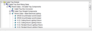
  1. Open the class editor, then select the desired path.
  2. Open any of the functions in the same subfolder that you want your function to be in.
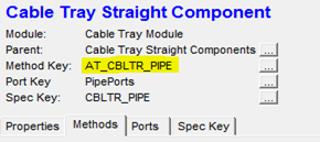
  3. Copy the name of the “Method Key”, then search for the files in your porject directory using notepad ++ or a similar tool, using the file extension .ini. This will locate the folder in your project directory that the class should be placed in.
  4. There are 3 files which you need to place information into to create the class. These are class.ini, methods.ini and speckey.ini (speckey.ini is only needed if your function requires you to get data from a database file).
  5. Create your new class by right clicking on the parent class and selecting “insert new component”.
  6. Enter a name and description. The name is the function that will be called from
    AutoCAD, it should have no spaces and be all upper case letters. The
    description is what will appear in the class editor, this name can include
    spaces and doesn’t need to be uppercase. For example my name is TEST_FUNCTION, and the description is “This is a test function”.
  7. Clicking  Ok will open your new class with default parameters associated with the parent. We need to change the Methods and the Speckey. To modify the methods click on the button ‘…’ to the right of it.
  8. This will open the method’s dialog box, click on the ‘new key’ button on the right side of the dialog box. The name asked for by the new window will follow the same rules as the name in step 6.
  9. Copy the same method key as the existing class you are basing your function off of. The functions called will stay the same as the ones in the method key you copied, they can only be changed from the methods.ini file.
  10. Repeat steps 7-9 for the speckey, the speckey name and the methods name can be the same. Like the methods the speckey can only be edited from its speckey.ini file. When done click the save button in the Class Editor.
  11. Open the class.ini file, new classes appear at the bottom of the file. Once you have found your class you can change the description, the method or speckey it uses and the picture that will be seen in the class editor. If no picture is desired
    then this line can be removed.
  12. Open the methods.ini file, the new methods appear at the bottom of the file. In your method you can change the file location and function name of the sub-method, such as the DRAW_METHOD. Change the desired sub method file location and function so that it looks like %APP_DIR%\file_folder\file_name ; FUNCTION_NAME
  13. Open the speckey.ini file. The DISPLAY_FIELDS indicate which fields from the
    database file are displayed when the function is run, the fields are shown in
    the order they are written, the data will then be sorted alphabetically starting with the left most column. SPECKEY_SCRIPT should be left alone. The SPEC_TABLE indicates which table from your database file information will be used from. The WHERE_CLAUSE filters the data from the selected table, this section works in the same way as an if statement. Only rows that satisfies the clause will be displayed.

Adding a function to AutoCAD Menus, Tool Paletts, Tool Bars and Ribbons

  1. In AutoCAD open Tools->Customize->Interface.
  2. Under the Command List select any command and choose duplicate under the right click menu.
  3. Select the duplicated command (it will have the larger Element ID #), then change the command name to one that describes the function (this will be what appears in
    the menus and tool palettes. It will appear as a description in the ribbons and toolbars).
  4. Change the macro so that it is ^C^C(at_Component_insert “AT_CABLET” “CLASS_NAME”),the first “” is dependant on which folder in the class editor you placed your class in. The second “” must be the name of the class that uses your function.
  5. Select a button image, this is what will appear in the tool palette and ribbon, if
    there is no premade image in the list that fits your function create one using
    the edit button.

    Note : any changes made to the command name, description or picture will not automatically update. The command must be replaced in all menus, tool palettes and ribbons.

Menus

  1. Under the “Customizations in Main File” select at_elect.cuix in the dropdown menu. This will allow changing menu items under “Raceways”.
  2. Open menus->raceways, then either create a new sub menu under raceways or open more sub menus to reach a desired location.
  3. Select your command from the Command List, then click and drag the command to the desired location.

Tool Palettes

  1. Open the desired tool palette, if it doesn’t exist create it using the customize
    palettes (from right clicking on the tool palette), right click the palettes
    box and select new palette. Name the palette to describe the tool set
  2. Now open the customize user interface window
  3. Select your command from the command list and drag it onto the tool palette

Ribbons

  1. Under the “Customizations in Main File” select at_elect.cuix in the dropdown menu.
  2. Open Ribbons->Tabs->Raceways, right click on raceways and select new tab. The tab name is what will appear on the ribbon
  3. Open Ribbons->Panels, right click on panels and select new panel. Name it the same as the tab you just created

Building the Ribbon Panel

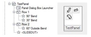
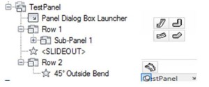
  • Ribbons are based on 3 elements, rows, sub-panels and the ‘slideout’
  • Rows
    • Functions placed in a row will appear left to right evenly spaced, with their order base on their position in the dialog top to bottom

Capture

    • Multiple rows on the same level will make columns

Capture

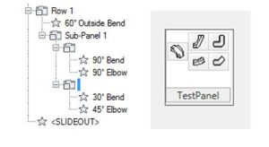
  • Sub-Panels
    • Sub-panels allow rows to be divided into multiple rows

Capture

  • SlideOut
    • Anything below the slidout will appear only when you place your mouse over the slideout, must be on new row that is beneath the slide out

Capture

  • All functions are added to ribbons by clicking and dragging into place

Tool Bars

  • works using the same principals of the ribbons, except that you can only use a single row and there is no slideout
  • create a new tool bar by opening the customize user inter face, going to at_elect.cuix. Open the Tool bars folder then right click on it and select new tool bar.
  • to place commands on your tool bar click and drag them to the desired location. adding “Flyouts” to the toolbar will create a dropdown similar to the ribbon slideOut when selected. Adding a flyout will also create a separate toolbar that is identical to what is in the flyout

How to add a new section and function to the support/topworks dialogue box

I will be doing this for a support, to do this for topworks repeat all of the same steps except start with topworks.ini instead of support.ini. In this post I intend to add a new function and section under the Cable Tray supports tab. To see the help file for this open support/Topwork browser and click on the “?”.

First open supports.ini in the folder “Network Drive”\Bentley\Plant V8i\Modules, the definitions for the support browser can only be place on the network drive,not the project drive. This will open a text document with multiple sections that look like classes. for example my [BASE] section looks like this:

[vb]

;//Base

[Base]

Description = Base Supports

Anchors and Guides = anchors.ini                                                                          Hangers =

hangers.ini                                                                                                Shoes =

shoes.ini

Base =basesupp.ini

Misc. Supports = miscsupp.ini

User Supports = Supports.ini

[/vb]

The [base] indicates that it is part of the base components so the system will search for the .ini files in the base folder. For cable tray the indicator is [AT_CABLET] so the system knows to search in the cableT folder (this is defined somewhere but I’m not sure where). All of the ini files must be in the correct folder for there functions to appear in the window.

Note the supports.ini file associated with user supports is not the same as the modules\supports.ini file because it is in the base folder

To add your section and functions place “desired section name = desired functions file.ini” under the overall heading. For example mine would be under [AT_CABLET] as MyFunction = Test.ini

The next step is to create the Test.ini file, I recomend copying one of the [base] ini files to use as a template then fill in the required fields. Only 3 fields are required:

  •  the identifier in []
  • Class name = AT_CLASS_NAME (this is the name of the class that will be called when the function runs)
  • Description = Function name (this is the function name that will appear in the supports/Topworks browser)

After this open the Class.ini file in your local project and create a class that has the same name as the one from the last step the class should look something like this

[vb]

[AT_SUPPORT_Test]

PARENT_CLASS  =BASE_SHOES_SUPPORTS

METHOD_KEY   =AT_SUPPORT_Test

PICT_NAME   =WEARPAD

CLASS_DESCRIPTION =Test Support Class

ISOLENGTH_KEY  =AT_SUPPORT_HANGER

SHOP_FLD   =1

SPEC_KEY   =TestSpec

[/vb]

Im using the wear pad class as my base, so I left some of the keys as they were default, we need to change the Method_key, Spec_key and class description so that it runs our function    The speckey is changed in your project directory inside of the folder defined earlier (mine is the CableT folder).The speckey will have the same formate as a regular speckey and should look something like this

[vb]

[TestSpec]

SPEC_TABLE  =  PIPE WHERE_CLAUSE =  GTYPE = ‘SUPT’ AND STYPE = ‘WEAR’ AND MAIN_SIZE = ‘6’

SPECKEY_SCRIPT  =  at_SpecKey_valves

DISPLAY_FIELDS =COMM_ID;TAG;MAIN_SIZE;COMP_LEN;LONG_DESCR;TAGNUMBER

[/vb]

For the method key copy the method key of the class your modelling your function on

[vb]

[AT_SUPPORT_Test] DRAW_METHOD       =  %APP_DIR%\Draw\SupTest ; at_CableTrayConnector
INPUT_METHOD      =  Common\SupTest ; at_Support_inputWearPad
PORT_METHOD       =  %APP_DIR%\Util\Ports ; at_Support_definePorts
ORIENT_METHOD     =  %APP_DIR%\Util\Orient ; at_HangerSupport_determineOrientation
PXF_IN_METHOD     =  XCHG\PXF\SuppIn ; PXF_IN_WEARPAD
PXF_OUT_METHOD    =  XCHG\PXF\SuppOut ; PXF_OUT_WEARPAD COORDS_METHOD     =  %APP_DIR%\Util\Coords ; at_HangerSupport_defineCoords
JSM_OUT_METHOD    =  XCHG\JSM\SupWearPad ; JSM_OUT_SupWearPad
EDIT_METHOD       =  Common\SupTest ; at_Support_editWearPad
ATTACHMENT_LOC_METHOD   =  %APP_DIR%\Util\attloc ; at_SaddleSupport_determineAttachmentLocation

[/vb]

I changed the name of the draw file and created a function to draw my desired support. I also changed the edit and input methods (they use the same file because they call different versions of the same dialogue) by altering what the dialogue asked for. When changing these file alter the ones on your project drive.

Note: the ATTACHMENT_LOC_METHOD applies only when something is being attached to the OBJECT THAT HAS THE METHOD. Ex attaching support A to Pipe B, will use Pipe B’s ATTACHMENT_LOC_METHOD and not support A’s ATTACHMENT_LOC_METHOD

Due to the note above I had to change the attachment method of each type of cable tray I want to attach to so that my support appears in the correct place. I changed my local project file by adding an if statement to each of the affected function so that it called a separate attachment function if they object was CableT and let the functions run normally if it wasn’t.

Note: When creating a support make sure to apply it to each type of object that it will be attached to. for example I had to try my support on all forms of cable tray such as straights, bends, tees and so forth