 This is my log on figuring out how to make new Electrical / Raceway (piping module!) components and I hope to help you know the ins and outs. From this, I made another post which is more “do this, do that, etc.” for those that just want to get things done. I needed to write down many notes, so I did so here as it is quicker to type and I can copy/paste stuff back out of this article as I needed the info.
Basically, my spec gen is broken and there is no help available to at the moment so how do I make a new component in the piping module/app? Electrical components seem to piggy back on this module as well. Since I will be referring my handwritten notes as this happens in spurts and I will need to refer to it in 6 months, I thought I would write things down.This will also be used to train on this stuff once I clear the way in our electrical department. So how do we get new specs, new drawing files etc. How is this hole spec, drawing, database thing linked? This too will be answered along the way for you to follow. If you know why my spec gen is broken let me know (here is a link to my exact woes which others have too)
This was written after going through an outdated Equipment tutorial (access via Start->Programs->Bentley->Plant V8i\Help Files\Equipment Component Customization Tutorial) This will soon to be rewritten – copy and pasted really – as I need an accurate copy of those too, corrected and posted from an electrical perspective and the link posted here. This is super-duperly written tutorial by Bentley -the format and pace was incredible (3-5 hours if programming is your schtick) – just so many details were wrong since I have a windows 7 machine, Access 2010, a central database behind the scenes and v8i. I think Bentley AutoPLANT forgot to update it. Anyway, with a bit of paper and ink, I muddled through it. Now, all those concepts apply but the places it is stored etc. are different for piing than the equipment module. Why do I want to use the piping module? Because equipment has several bugs like it redrawing USERDEFINED components after editing the component info on placed objects (it puts them back on it’s layer instead of the layer specified. Also – if you have ever played with the Annotations in piping vs. equipment you will soon notice a HUGE difference – piping you can solve the world’s problems etc. so we really want to understand how to make piping components.
Getting things understood
I copied the project to my own local computer with my own local SQL Server and my own Report Services (many other blogs posts exist here on how to do this) and I did use the product called Beyond Compare and Notepad++ to ensure my settings etc. pointed to the new project however the modules.ini file still had old entries – so look in this file for paths etc. that point to old directories %PROJECTDIR%\Config\modules\modules.ini
Step 1. Edit the MDB file
I am trying to edit the mmlights.mdb spec. In there is a light that I wish to make my own from. I copied the row then changed the following fields
- TAG=LED-14
- LONG DESCRIPTION=LED Test Light 2
- PIPE_OD_M, COMP_LEN, FIXT_LEN,FIXT_WID, FIXT_WID, LAMP_WAT, SCHEDULE,
- SHORT_DESC=LED FLOOD
- CLASS_NAME=ELB_FLOODLIGHT_PLTFMNT (which used to be AT_FLO…. but I want everything we customize to use the company prefix).
- SYS_ID – just change the first letter – really this should be autogenerated and will be once I get my Specification Generator program working (arrggg!).
- CATALOG_NAME=ELB-Custom (again we want to make our own catalog from the specs eventually – so this is preparing for the future
CLASS_NAME=ELB_FLOODLIGHT_PLTFMNT – this is really important throughout this article
Then edit the table called “SpecClasses” and add the new class for the Lights Group (copy and paste an existing row) – and ensure the class name as is typed above.
Step 2. Start your class editor
Start->Programs->Bentley->Plant v8i->Tools->Class Editor
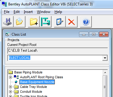
Open your project by selecting the directory – in my case the local project is on C:\ELB Test Local\ELECT LOCAL\ also known as %PROJECT%
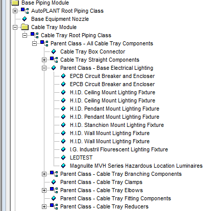
- Added a new component called our class name and the description is LEDTEST
- Make a quick 16 bit bmp to keep the class editor from complaining each time you load the new class called %PROJECT%\Config\modules\CableT\Pictures\ELEC_LIGHT.bmp
- Open up an item that you copied your row from in the spec gen database and copy by selecting the same options using the … boxes to the right of the text next to the diagram. From here we will customize things
- Parent
- Method Key
- Port Key
- Spec Key
- On the Properties tab, edit your PICT_NAME=ELEC_LIGHT (name of your bmp without the extension)
- Change the owner column for the CLASS_DESCRIPTION – it might be already set to the new class name.
- This NOW adds a file to your %PROJECT%\Config\modules\CableT directory called class.ini, methods.ini, ports.ini, speckey.ini (go – take a look! – open them up permanently in Notepad++ because it tells you when changes are made there. These are the files that help you learn what the dickens is going on.)
- Click on the Spec Key: … button
- click new key and give it the name LED_LIGHT
- it will ask you from where you wish to copy info from – choose the original one which was FLDLGHT_PLTFMNT
- click OK and it happily copies it from the main speckey.ini file and puts it into our new custom one at %PROJECT%\Config\modules\CableT\speckey.ini (yes – go look and keep it open in Notepad++)
- what is this? where is this keyword FLDLGHT_PLTFMT? This is yet a further grouping of data on how to find the spec in the spec tables
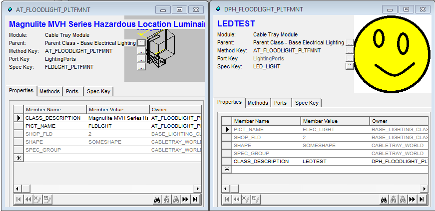
- Here is a screenshot of what it might look like from the old class to the new class with our new name. I like my picture better.
Now – as I said, look at your new speckey.ini file
[ini]
[LED_LIGHT]
DISPLAY_FIELDS = LAMP_WATTAGE;MAIN_SIZE;TAG;LONG_DESCR;PIECE_MARK
SPECKEY_SCRIPT = at_SpecKey_valves
SPEC_TABLE = LIGHTING
WHERE_CLAUSE = GTYPE = ‘LTFL’
[/ini]
Now you will recognize the patterns and key words entered in step 1 above when you copied the old light row to the new row in the spec .mdb file. LOOK AT THE WHERE CLAUSE! Note that it didn’t pull up in the Spec Key tab (diagram above) – but if you tried to place a component before and it didn’t pull up a table because there was only one item in the query, it will now! Very cool to see this all working – at least mine did.
You can adjust all sorts of things in those 4 lines.
I don’t know what SPECKEY_SCRIPT is yet. (sign up to my RSS if you want updates)
PLEASE COMMENT BELOW IF IT DOES NOT WORK – I WANT THIS TO ALL WORK PERFECTLY WHEN YOU TRY IT TOO.
Step 3 – adjust the routines that draw
Now we are in research mode again since the stuff above was written after I had already figured things out. I was just going crazy remembering all the links so I wanted to write this all down.
- In class editor, click the Method Key … button
- the AT_FLOODLIGHT_PLTFMNT – look at the DRAW_METHOD
- while we are this, let make our own – I suspect it will copy the AT_FLOODLIGHT_PLTFMNT to a new one in our methods.ini file
- Click New Key, call it ELB_LED_LIGHTS
- Sure enough – widen the box so you see the title – see? “Select a Method to copy from” and select AT_FLOODLIGHT_PLTFMNT and click OK
- Click OK
- Click the save button in your Class Editor
- Now click OK and look at your methods.ini – see the new section? I am getting the hang of this now too. It makes changed in your class.ini, speckey.ini as well
- [ini]
- [ELB_LED_LIGHTS]
DRAW_METHOD = %APP_DIR%\Draw\ElecLghtDraw ; at_Floodlight_draw
JSM_OUT_METHOD = XCHG\JSM\ElecLghtOut ; JSM_OUT_FLOODLIGHT
ORIENT_METHOD = %APP_DIR%\Util\Orient ; at_LightFixture_determineOrientation
PROP_METHOD = Common\Compprop ; at_ComponentProperties_set - [/ini]
- Lets go edit the file and add a MsgBox(“Hello”) vb or drawing ebs script and see if we get what we think should happen- some action. I like Visual Basic because you can see changes immediately
- If you use Notepad++ you can find all *.ebs files that contain the name of our function which is at_Floodlight_draw in your DRAW_METHOD line above – you can verify that it is in the directory it lists – and it is.
- C:\Program Files (x86)\Bentley\Plant V8i\Modules\CableT\piping\draw\ElecLghtDraw.ebs
-
%APP_DIR% is the AutoPLANT application like PIPING, EQUIP etc.
- Change the lines of code in that file to include the line MagBox(“Hello”) & save
-
[vb]</li>
<li>Sub at_Floodlight_draw()
MsgBox("Hello")
Call at_ElecLght_draw ("Floodlight")
End Sub</li>
<li>[/vb] - TEST: Now go and place that same light you did before in AutoPLANT (no need to restart for this test – since we are changing the original file
- – you should use software versioning control software – I am so changing original files is not a big deal – I just revert if I completely break everything. I like SourceTree which is a github / mecurial front end – if this is new to you please go figure this part of programming/control out – it is very very important and so easy to use with a little tenaciousness. PLease use windows backup too – but also use some sort of version control)
- Sure enough – this is the file – so lets move a copy to our own area. Undo the MsgBox change and save the file.,
- Copy the file from
- %APP_DIR%\Draw\ElecLghtDraw to
- %project_root%\Config\modules\CableT\piping\Draw (you will see there is already a Draw directory here)
- rename the file to include a postfix of ELB or ElecLghtDraw_ELB.ebs
- Now edit it and put BACK a new MsgBox(“HelloELB”) message
-
[vb]</li>
<li>Sub at_Floodlight_draw()
MsgBox("HelloELB")
Call at_ElecLght_draw ("Floodlight")
End Sub</li>
<li>[/vb] - Connect this new file up by editing your projects %project_root%\Config\modules.ini file by using your class editor:
- click on the Methods Key … button, then edit the Method DRAW_METHOD row to the ScriptPath=.%project_root%\Config\modules\CableT\piping\Draw\ElecLghtDraw_ELB
- NOTE THERE IS A MISTAKE HERE (I left it here – it gets corrected and paths are explained about 6 bullets ahead)
- Save and now the Methods.ini file will be updated like this. Don’t change it directly – use the Class Editor (see the help guide and you will find our that it uses a temp database that overwrites your changes when you close the class editor)
- [ini]
- DRAW_METHOD = %project_root%\Config\modules\CableT\piping\Draw\ElecLghtDraw_ELB ; at_Floodlight_draw
- [/ini]
- Lets test. You have to restart AutoPLANT/AutoCAD.
- When I went to place my new component, I got the following message – which shows me the paths that it follows to find our .ebs file – which is really useful. I obviously have to fix something but I am not sure what since the file is in the proper place. It has no .ebs in the file below – is this it?
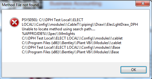
- HA HA! – The mistake I made was – when typing the path – you have to start at the paths it looks in – which is in the diagram above – hence, we SHOULD have put the string piping\Draw\ElecLghtDraw_ELB – lets try %APP_DIR%\Draw\ElecLghtDraw_ELB … yes, that works too.
-
Paths are important to understand – now we know more – that was one of my fundamental questions as I saw lots of other examples that edited the core files. Learn about paths and customize your files to move along with the specs and/or with at least the project and not everyone’s computers.
- Now we can finally do the last step – customize the .ebs file to draw the lights the way we need them.
- If you use Notepad++ you can find all *.ebs files that contain the name of our function which is at_Floodlight_draw in your DRAW_METHOD line above – you can verify that it is in the directory it lists – and it is.
Step 3 – modify the drawing routines\
{in progress – but if you go to the tutorial on equipment I think a lot of this is explained VERY WELL – even though the instructions are riddled with outdated stuff – or maybe it is just that I have a diff computer config – anyways go through those instructions as are beyond insightful. access via Start->Programs->Bentley->Plant V8i\Help Files\Equipment Component Customization Tutorial}
- Using the class editor – edit the relevant item and in the methods tab, select the row: DRAW_FUNCTION – change the Function Column to at_LED_draw
- Edit the our new custom .ebs file and make a new Sub at_LED_draw() subroutine
- Test it with a MsgBox if you want – it works
Step 4 – Add items to the menu in AutoPLANT / AutoCAD
- this is the really frustrating part. Currently, because I don’t know one step, I cannot help you either.
- If you edit the menus you so do via the (assume AutoCAD classic menus and no ribbon) Tools->Customize->Interface (CUI grey/black icon)
- [optional] Narrow down your list by selecting All customizations pulldown and choose the one you are working on (in my case at_elect.cuix)
- Expand the top left set until you get to the one you like and want to copy – choose it on the left .Mine is called Pendant Mount
- On the right, your Macro property might have a function or shortcut listed here.
- In the macro property on the right, In my case it is ^C^CAT_HWLIGHT_PNDTMNT . So where do you find THIS abstraction? You need this because what you are really requiring is a command that this function points to. These definitions are listed in *.mnl files
- Now find this AT_HWLIGHT_PNDTMNT string with Notepad++ in .mnl files .. wait … wait longer … longer … get a coffee … ok – here is the file: C:\ProgramData\Bentley\Plant V8i\elect\at_elect.mnl . Now open it and you will see a defun (define function) that abstracts it to(at_Component_insert “AT_CABLET” “AT_HWLIGHT_PENDANTMOUNT”)(princ)Here is a blog of lisp newbie for those starting out trying to interpret this line.
- You CAN copy and paste the new item customized into the AutoCAD command line as(at_Component_insert “AT_CABLET” “ELB_UIOC_GENERAL”)(princ)
- But here is the rub, an error occurs after it tells you to pick a point and it is PIP_0701: Invalid Size for Demo Version .
- if you then re-use another class that is already working and change all the class info etc. for it to point to the new stuff you made … then it works fine and you don’t get this error message, however your CLASS= item on screen 2 of your component edit WILL SHOW THE WRONG CLASS -it shows the one you reused.
- If ANYONE has any clues, please leave a message at the bottom of this article.
- This error, if it is searched shows up in the c:\Program Files (x86)\Bentley\Plant V9i\Bin\R18\at_aiso.arx file which is binary – so there must be a way around this or to get some understanding on this from Bentley.
- ALSO – keep in mind – I have another odd “Demo” message that appears when I double click a component in my Class Editor window – it says “Data Widgets 2.0 Unlicensed Copy – For Demo Use Only”. This says Sheridan Software but it is now owned by Infragistics and I the tool has a different name now.
Step 5 – modify the routines that update database values from specs
{in progress – lets finish step 3}
Pingback: Bentley Search Path for .ebs files - elbsolutions.com Project List & Blog