This tutorial / step-by-step can be used as a training manual. If you want the log book style article on how to figure all this out see the other article. No lesson in Bentley Docs describes this. There is a help file on linking in the Equipment Modules as a .ebs drawn entity and how to edit those classes. This is for the Piping module side of things for Electrical items – the concepts can be used for any piping module application.
Step 1. Start Class Editor and gather info
- Open your Class Editor
- Open your project under the menu File->Open
- Expand the hierarchy on the left to a sample component that you wish to mimic or use as a base. In my case, the HID Ceiling Mount Lighting fixture.
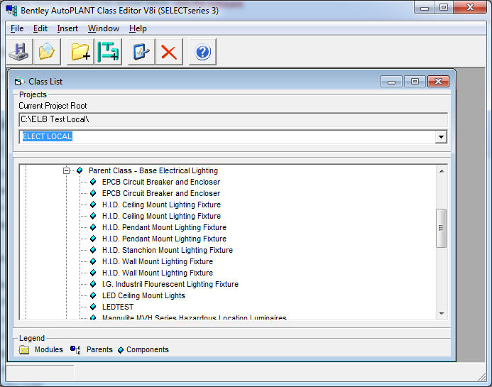
- Double Click the component and move it to the left of the screen
- Right Mouse click on the same component and choose Insert a new component and position the screen to the right
- Type a new name like and I suggest you do NOT prefix it with AT but with a company specific prefix – in my case ELB and I will keep the rest the same. I am naming it ELB_LED_CEILINGMOUNT
- Make all the Parent, Port Key, Method Key and Spec Key entities the same as the original item – again – 2 screens are assumed to be open if all the steps above were followed. This is done by clicking the four … icons to the immediate left of the picture
- Go back to Method Key by clickling …:
- Click New Key
- Enter ELB_LED_LIGHTING1, choose the new one and click OK
- choose the module to copy from as the one from the screen on the left
- click OK
- Click on Methods tab
- scroll down to the DRAW_METHOD row – and put the following in Script Path
- %APP_DIR%\Draw\ElecLEDLghtDraw_ELBS
- Leave the function name at at_Floodlight_draw
- Copy the original .ebs drawing file from its location to %APP_DIR%\Draw\ElecLEDLghtDraw_ELBS.ebs (you can figure out where the original is by edit the same row of the original class that we are trying to mimic)
- Go back to the Spec Key by clicking …:
- Click New Key
- Enter ELB_CLNG_LED, choose the new one and click OK
- choose the module to copy from as the one from the screen on the left
- click OK
 I am not sure why the picture defaulted to the last one I made, but picking it must be done OUTSIDE of the class editor. DO NOT EDIT THE TEXT FILES CREATED BY CLASS EDITOR WHILE EDITING
- Press Save
- Close the Class Editor
- Edit the newly formed files in %PROJECT_ROOT%\Modules\CableT\class.ini
- Add to the new section an entry with the name of the file (or most of the name)
- PICT_NAME = EMERSON
- Oh, make a 16 bit bmp using Microsoft Paint and place it in %PROJECT_ROOT%\Modules\CableT\piping\Draw\lumisave_bl420.BMP
- Edit the %PROJECT_ROOT%\Modules\CableT\speckey.ini file
- adjust the where clause and in my case I am setting it to
WHERE_CLAUSE = GTYPE = ‘LTCM’ AND STYPE = ‘LED1’ - again – I am not sure why this cannot be edited using the class editor. If anyone knows, please leave a comment
- adjust the where clause and in my case I am setting it to
- Click on Methods tab
Step 2. Adjust Spec database to match
The last step above is the link to the spec catalog
- Open the Spec Database. In my case it is %PROJECT_ROOT%\Spec\mmlights.mdb
- copy and paste a relevant row – a row like the one that the original CLASS that was copied in the first step at the top.
- EDIT the GTYPE to be LTCM
- EDIT the STYPE to be LED1
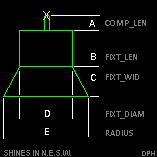
- change dimensions to match the figure above. Use any column. I have retyped the list from the help file from Bentley because I found it by accident and it was poorly generated and I don’t remember where it was located.
- Adjust PIPE_OD_M as the size of the nub at the top – note this is hard coded and not a variable
- Adjust COMP_LEN to the A dimension
- Adjust RUNG_SPACE to the D dimension
- Adjust RADIUS to the E dimension
- Adjust FIXT_LEN to the B dimension
- Adjust the FIXT_WID to the C dimension
- EDIT the TAG value to ?? LED-16 – not sure full extent of this field yet
- Adjust the first character of the Sys ID – this will mean a repair function will need to be performed on using the spec tool except mine is broken – so that is why I am doing the whole procedure this way (the geeky text method).
- Adjust the CLASS name to be that of the one we started with at the beginning of this article
- Edit the SpecClasses table – add an entry similar to the one we came from – in my case GroupName=Lights, ClassName=ELB_LED_CEILINGMOUNT
Step 3. Add a menu item in AutoPLANT/AutoCAD
- Edit the User Interface
- Is the toolbar to 2D Drafting & Annotation? click on the manage tab, then CUI icon (User Interface)
- Is the toolbar the AutoCad Classic one? click Tools>Customize->Interface
- above the top left list, choose the pull-down item at_elec.cuix
- In the upper left list, expand items until you get an item you would like to copy. Note it’s name
- In the bottom section, find that same command you would like to duplicate, press the R-Mouse Click “Duplicate”
- in my case, I want to duplicate a sub-menu flyout – so right mouse click the item above where your sub-menu is in this case, Raceways->CableTray and choose New Sub-Menu
- – name it LED Lighting Fixtures
- Thinking back to 5 – rename the new item in the bottom list – there will be 2 of them. Choose the one with the largest property name “Element ID” – that is the new one.
- Rename it by changing the Name property – LED Lights Set 1
- Change the Macro property to ^C^C(at_Component_insert “AT_CABLET” “ELB_LED_CEILINGMOUNT”)
- there must be a way to edit the .mnu and .mnl files – I will update this if that is the better way – the at_elect.mnl file has a level of abstraction which is how I figured out the long command.
- Drag this LED Lights Set 1 item into the new sub-menu (if you made a new submenu) or into place in the upper left list.
- Click OK at the bottom
- Change back to the View Type Autocad Classic
- Restart AutoCAD/AutoPLANT (picks up the new class.ini file changes) if you get an error that it cannot filed any module data in the class ini files- and then it lists the paths it is trying to search
- When it loads, don’t forget to set the Spec to mmlights under the RaceWays->Setup->Component Setup window
- Check if your new menu item works to place a light using the new menu item
- PIP_0701: Invalid Size for Demo Version eror occurred – if you get this error, you most likely changed the Class name to something that offends AutoPLANT in some way. I don’t know how to solve this at this time (TODO:) so I changed the GTYPE and STYPE in my spec tables to make those lights (components) show up along side another menu item that used to only be one item – now it has a few more.
- put the menu item back to the verbose but old method with the old class name that now has your new parts as part of it or ^C^C(at_Component_insert “AT_CABLET” “AT_FLOODLIGHT_PLTFMNT”)
- Note that the command ideas work – it is somewhere in the details. I have spent a couple hours trying all sorts of scenarios to make this wok and looking for other config files etc. To no avail. Lets continue
Step 3. Generate a Spec Catalog
TODO: My spec gen is broken – so I can’t even start to tell you how to do these steps.
Step 4. Adjust the Drawing Routines
TODO: This is a very involved step. Basically, the drawing routines can be located by following these steps
- In AutoPLANT, open double click on your component
- Go to page 1 of 2 of the dialogs that appear and write down you CLASS= parameter.
- Open your Class Editor and your project within it
- Expand the Class Editor hierarchy to the specific one that matches the CLASS=parameter above
- Double click on it and go to the Methods tab
- Scroll down to the DRAW_METHOD row and write down the items in the Function and Script Path columns. This represents the function name that you need to edit and the file location (file location needs to have .ebs added to it)
- REMEMBER TO FOLLOW Best Practices when changing code! See this link.
Other things you need to know is that this is all VB6 which is quite old, but works well. The vb language reference for Bentley is fairly well done and is located in a Windows Help file by clicking on
Start->Programs->Bentley->Plant V8i->Tools->Basic Language Reference Help
If you are just starting out, I suggest the following tutorial. Do it as an exercise it is the equipment module, but the tutorial is so well done, it completely applies to getting you ready to do the piping module changes – which this article is all about.
Start->Programs->Bentley->Plant V8i->Help Files->Equipment Component Customization
Before you do this tutorial, if you have never worked with Equipment, do the following tutorial first
Start->Programs->Bentley->Plant V8i->Tutorials->Equipment Tutorial
Step 5. Edit the Component Edit Dialog
TODO: yet to be finished-just writing down a place holder for me when I pick this up again.