AutoCAD auto cleanup – a script on close

Research links:

  • talk of general cleanup that one should do
  • triggers in AutoCAD are called reactors (this is a good starter article)
  • A colleague mentioned not to do anything that takes up too much time on a document close reactor – because it triggers AFTER the close has been issued.
    • I suggested on a save? And the answer was yes, overwrite the qsave function and call a qsave at the end of that routine.
  • we are looking for a drawing reactor – when the doc saves. It mentions to use the vlr-types command to return a complete list of available reactor types.
  • a “before close” reactor … almost exists – read this. Yes – this is the ticket. Change “CLOSE” to “QSAVE” or “QUIT” … or all 3 if you wish. It works.

Continue reading

Adding text box input to a function

1. Start by finding the function that runs the dialog box in AutoPlant, for me this was the “H.I.D. Stanchion Mount Lighting Fixture”.

2.Open Bentley AutoPlant Class editor.

Capture1

3.Find the function in the “Class List” window.

4.Double click on the selected class to open the class properties window.Capture2

5.After opening the window select the methods tab.

6.Using the “script path” column find the directory and file associated with the INPUT_METHOD.

7.Copy this file to your working directory and rename it.

8.In the class list window find and open the class associated with your functions.

9.In the window that was just opened click on the button next to “Method Key”, this will open the Method list window.

10. In the method list window click on the line next to the *.

NOTE: Once you have clicked on the line, clicking on anything other than a different part of the line or the update button at the bottom WILL crash the class editor.

Capture3

11. Under the “method” column write INPUT_METHOD, this name is required because AutoPlant will associate it with one of the predefined method types that can be seen in the previous window.

12. Under the Function column write the description of the function.

13. Under the script path write %APP_DIR%\Files_folder\File_name, %APP_DIR% indicates that the file is in your overall working directory, it should be left as %APP_DIR% and NOT be replaced with the directory path.

14. Click the “Update” button in the bottom left conner of the window, then click Ok to exit the window.

15. Click the save button in the top left of the Bentley Class editor window, if open AutoCAD/AutoPlant must be closed and restarted for the changes to take effect.

Bentley Autoplant changing SysID’s – a way to do so in VBA code

OK – so I FINALLY have the whole mystery solved of what happens to SySID’s (sys id’s) in the front end (generation) and use (in DWG model files). Ideally they should match – so if you can’t change the source (out of my control) let try to change the destination?? Lets investigate.

First, I have needed to understand where Bentley puts all their data in AutoCAD. Finally I have an excuse to finish my investigation. I would like to change my Sys’IDs for a set of components so that the match the Spec Gen ones. So due to a situation out of my control (we simply wanted the Long Description changed), the SyS ID’s were all changed and it is more work to get them changed at the source than just change them in the DWG or AutoPLANT model. So lets look for them, find them and change them and heck, why not change some other items along the way like that Long Description.

In this article, lets look at all the XDATA apps that Autoplant uses. It discusses how to know what they are and what all the values are. Low and behold – the storage. Currently this article does not look at changing the values – that will come VERY shortly. Continue reading

Specification Generator or Spec Gen Talk about Sys IDs

A Bentley article that talks about components not getting updated with Spec Gen and how the sysId plays into this. It is a great discussion about how sysId’s are generated used and how they affect things. There are links that take the discussion further and show more insight in how Bentley’s system was created in order to do customization.

Before I gave some catalogs to the Spec Integration team, I had to regenerate the system IDs. WHat happens if you don’t? It deletes the duplicates – so poof – a whole bunch of specs could disappear on a copy/paste. So it is important to change a column that affects the SYS id which is listed in the MDB file under the DefaultSysIDs table. Note that Short in once counted and Long Descriptions on both did not count. Use the tool under the File Menu of the Specification Generator to randomize these values for you. It can be run on Catalogs and/or Specs at the same time.


Bentley Search Path for .ebs files

When I was making new components from scratch, I made an error in the search path and got an error popup – but it revealed something I suspected – an object oriented structure of Bentley where you could override and add classes and associated files – in this case .ebs files. This lists the search paths it uses for finding ebs files. Interestingly, it FIRST searches a directory with the same name as the spec IN THE SPECS directory. This means … that if you have ebs files you can have them travel with the spec independent of the project.

In the context I am working with – I was told – no this cannot  be done (even though it clearly can) so rather than change the world leaps at a time, I stayed safe and put things on the CableT\modules directory instead – a leaf in the project because of the people in the project – they are VERY conservative and they don’t delve into this level.

Looking below – we also see that if you have a company wide change for EVERY project – putting it on the c: drive is ok too. DO NOT put it in multiple places because you might drive the following group(s) who use this project insane when they delete functionality and it… it does not disappear!

Search path order:

  • %APPROJDB%\Spec\Mmlights
  • <project dir>\Config\modules\cablet
  • c:\Program Files (x86)\Bentley\Plant V8i\Modules\cablet
  • <project dir>\Config\modules\base
  • c:\Program Files (x86)\Bentley\Plant V8i\Modules\base

Continue reading

SMO for SQL Backup … of sorts

[Latest Edit Feb 14th] So, I go to edit a few Stored Procs on my MSSQL database and… errors – table missing – what? I seems over the weekend, all the databases were reset to some time in the past – this means 30 SP’s and 20 tables on our dev environment have – poof vanished – an honest mistake due to a communication misunderstanding. Not a big deal – everything is version controlled. It was the testing data that was lost and that people are semi-using at the moment that really gets my goat and makes me want to pull my hair out. I had a set of data that was perfect for making the next module.

So I searched for backup routines and since I use c# and think the SMO addition is so cool, I found some more great links – and the code worked in < 10 minutes each. Continue reading

Working with the Bentley Project Database and its effect on Update from spec

Adding new fields to the database

Adding new fields to the database is useful in cases were you more information about a component, but there is no corrosponding field in the database to the one in the specs.

If you know where your database is you can skip the first 3 steps> To create a new field in the database:

  1. Open the “Bentley Project Administrator”. Continue reading

How Bentley AutoPLANT integrates a new class, methods and speckey WITHOUT editing the core program files

Lets assume that a new spec was created. AutoPLANT has a very clever structure to its files so that the core ones that come with AutoPLANT need not be touched. It also helps when new specs, ebs, classes etc. are added (specs beyond just adding or changing dB rows). This article outlines how to integrate a new component where a new class was created. There is already an article which outlines how to create a ‘new spec’ (a complete one which includes class/ini sections, ebs files and mdb rows) to do this AND there is an article that outlines how that last article was figured out, so that you too can do find out more complicated classes like joints etc. for yourself.

Lets assume that you have all your files / edits ready to go. A pseudo and realistic example is at the bottom. Continue reading

How to add a new section and function to the support/topworks dialogue box

I will be doing this for a support, to do this for topworks repeat all of the same steps except start with topworks.ini instead of support.ini. In this post I intend to add a new function and section under the Cable Tray supports tab. To see the help file for this open support/Topwork browser and click on the “?”.

First open supports.ini in the folder “Network Drive”\Bentley\Plant V8i\Modules, the definitions for the support browser can only be place on the network drive,not the project drive. This will open a text document with multiple sections that look like classes. for example my [BASE] section looks like this:

[vb]

;//Base

[Base]

Description = Base Supports

Anchors and Guides = anchors.ini                                                                          Hangers =

hangers.ini                                                                                                Shoes =

shoes.ini

Base =basesupp.ini

Misc. Supports = miscsupp.ini

User Supports = Supports.ini

[/vb]

The [base] indicates that it is part of the base components so the system will search for the .ini files in the base folder. For cable tray the indicator is [AT_CABLET] so the system knows to search in the cableT folder (this is defined somewhere but I’m not sure where). All of the ini files must be in the correct folder for there functions to appear in the window.

Note the supports.ini file associated with user supports is not the same as the modules\supports.ini file because it is in the base folder

To add your section and functions place “desired section name = desired functions file.ini” under the overall heading. For example mine would be under [AT_CABLET] as MyFunction = Test.ini

The next step is to create the Test.ini file, I recomend copying one of the [base] ini files to use as a template then fill in the required fields. Only 3 fields are required:

  •  the identifier in []
  • Class name = AT_CLASS_NAME (this is the name of the class that will be called when the function runs)
  • Description = Function name (this is the function name that will appear in the supports/Topworks browser)

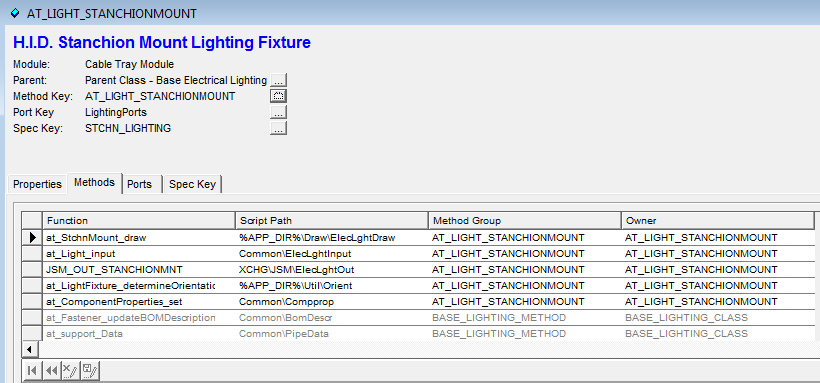
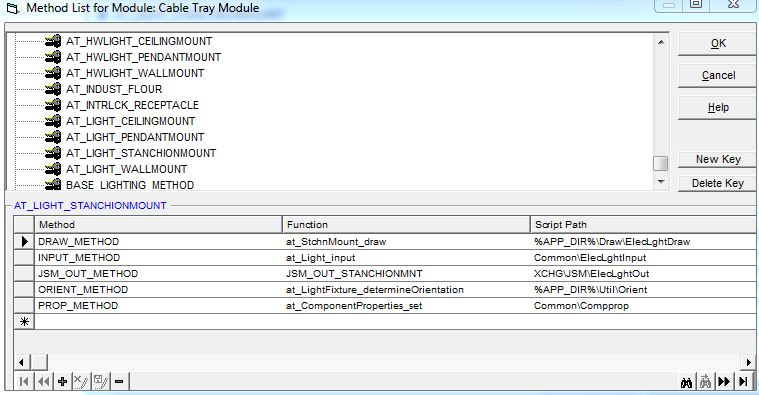
After this open the Class.ini file in your local project and create a class that has the same name as the one from the last step the class should look something like this

[vb]

[AT_SUPPORT_Test]

PARENT_CLASS  =BASE_SHOES_SUPPORTS

METHOD_KEY   =AT_SUPPORT_Test

PICT_NAME   =WEARPAD

CLASS_DESCRIPTION =Test Support Class

ISOLENGTH_KEY  =AT_SUPPORT_HANGER

SHOP_FLD   =1

SPEC_KEY   =TestSpec

[/vb]

Im using the wear pad class as my base, so I left some of the keys as they were default, we need to change the Method_key, Spec_key and class description so that it runs our function    The speckey is changed in your project directory inside of the folder defined earlier (mine is the CableT folder).The speckey will have the same formate as a regular speckey and should look something like this

[vb]

[TestSpec]

SPEC_TABLE  =  PIPE WHERE_CLAUSE =  GTYPE = ‘SUPT’ AND STYPE = ‘WEAR’ AND MAIN_SIZE = ‘6’

SPECKEY_SCRIPT  =  at_SpecKey_valves

DISPLAY_FIELDS =COMM_ID;TAG;MAIN_SIZE;COMP_LEN;LONG_DESCR;TAGNUMBER

[/vb]

For the method key copy the method key of the class your modelling your function on

[vb]

[AT_SUPPORT_Test] DRAW_METHOD       =  %APP_DIR%\Draw\SupTest ; at_CableTrayConnector
INPUT_METHOD      =  Common\SupTest ; at_Support_inputWearPad
PORT_METHOD       =  %APP_DIR%\Util\Ports ; at_Support_definePorts
ORIENT_METHOD     =  %APP_DIR%\Util\Orient ; at_HangerSupport_determineOrientation
PXF_IN_METHOD     =  XCHG\PXF\SuppIn ; PXF_IN_WEARPAD
PXF_OUT_METHOD    =  XCHG\PXF\SuppOut ; PXF_OUT_WEARPAD COORDS_METHOD     =  %APP_DIR%\Util\Coords ; at_HangerSupport_defineCoords
JSM_OUT_METHOD    =  XCHG\JSM\SupWearPad ; JSM_OUT_SupWearPad
EDIT_METHOD       =  Common\SupTest ; at_Support_editWearPad
ATTACHMENT_LOC_METHOD   =  %APP_DIR%\Util\attloc ; at_SaddleSupport_determineAttachmentLocation

[/vb]

I changed the name of the draw file and created a function to draw my desired support. I also changed the edit and input methods (they use the same file because they call different versions of the same dialogue) by altering what the dialogue asked for. When changing these file alter the ones on your project drive.

Note: the ATTACHMENT_LOC_METHOD applies only when something is being attached to the OBJECT THAT HAS THE METHOD. Ex attaching support A to Pipe B, will use Pipe B’s ATTACHMENT_LOC_METHOD and not support A’s ATTACHMENT_LOC_METHOD

Due to the note above I had to change the attachment method of each type of cable tray I want to attach to so that my support appears in the correct place. I changed my local project file by adding an if statement to each of the affected function so that it called a separate attachment function if they object was CableT and let the functions run normally if it wasn’t.

Note: When creating a support make sure to apply it to each type of object that it will be attached to. for example I had to try my support on all forms of cable tray such as straights, bends, tees and so forth

Annotation in AutoPlant

This is the process I used to find out how the annotation Instrument Balloons function works:

  1. started by opening tools->customize->interface to find the function name for the menu button “Instrument Balloons…”. I found the function “AT_Annot_InstrBubble” was accociated with the menu button.
  2. After searching for the function I found it in C:\ProgramData\Bentley\Plant V8i\elect\at_elect.mnl, which is a LISP file, the function was contained within lines such as “Line 473: (defun c:AT_Annot_InstrBubble_T1   ()  (at_Piping_annotateComponent “InstrumentBubble_T1″)  (princ))”.
  3. By searching for “InstrumentBubble_T1” I was able to find the file annotate.ini under C:\Program Files (x86)\Bentley\Plant V8i\Config\metric\piping (metric is unit system your drawings are set in, can also be imperial or mmetric), this ini file contained the classes for “InstrumentBubble_T1”
  4. the only line that contains a function call is the “textFunction = at_Component_annotateInstrumentBubble”, there are 2 files that contain this function. The first is Annotate.ebs, this has the function definition of at_Component_annotateInstrumentBubble and other annotate functions. The second file is methodes.ini under  C:\Program Files (x86)\Bentley\Plant V8i\Modules\Base. The methods.ini file shows that at_Component_annotateInstrumentBubble is related to the Ann_InstrumentBubble_Method, which is part of the overall base commponents method.
  5. To find which sub methodes are used I went into the respective files and in each function I placed a message box outputing the function name. Running the desired function I determined that 2 functions from this method were called, then other functions I haven’t been able to Identify run afterwords (these functions are not part of the Base_Component_Method). The functions that I can identify create the first dialog box, the functions that run after the dialog box open a second dialog box then draw the annotation.
  6. Base_Component_Method acts as the method key for the parent class of each module such as HVAC or CableT.There are no functions in this method key that contain a draw function or call a draw function.