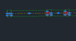
 If a piece of rigid PVC conduit is placed in Bentley AutoPLANT, then you will see a red dot or placeholder get added along with it. This comes out in the BOM as a glue. If you place enough of these, it counts the welds. How does this work – can I do the same for kits of stuff like joints or fasteners along with each piece of cable tray.
This is a log of my discoveries on ripping AutoPLANT apart to see how it works so I can create my own components like these so that items can be included as attachments in the MTOs or BOMs created.
Go exploring for root data
First, if you place down a few lengths of this, they will appear in the PIPING table as an entry for the conduit and one for the glue. If you double click on them you can find the component names, classes and which spec table they came from. If you delete a piece of pipe, the glue entry deletes too – which means there is a relationship somewhere as well that exists (not sure how yet).
What I really like about the fastener idea – is that if you double click on a component it exposes the “Existing” check mark – or at least one can expose it so that we can use this flag to include or exclude an item from a custom BOM.
If we take info from the diagram above, here is the root data for this article.
LEFT PIPE:
COMP_ID=AT_HH033Y3V_CZ, MODULE=at_COND, CLASS=AT_COND_RIGIDPVC, SPEC=Mmcond, CATALOG=CONDUIT
LEFT RED GLUE:
COMP_ID=AT_HH033Y3V_DO, MODULE=at_COND, CLASS=AT_GLUE, SPEC=Mmcond
Lets leave it like this for now.
Find these items in the class editor
Start the class editor and do a Edit->Find to look for the AT_COND_RIGIDPVC – there it is under “Conduit Module->Conduit Rigid Piping Class->All Conduit Components->Conduit Pipes->Conduit Rigid”.
Now lets find AT_GLUE. Is in class editor – oh – yes – but in a parent MODULE (not a CLASS – odd – since if you look above, the class is AT_COND)
AutoPLANT Root Piping Class->Parent Class – All Base Components-Parent Class – Base Fasteners->GLUE FASTENER and there is another child of that called Glued Fastener (class=AT_GLUE_COND).Note the Spec Key=NONE for this class so it does not come from a spec!
Now, using Notepad++, I notice that the .ebs files show nothing, but looking in all files, here are the results from the C:\Program Files (x86)\Bentley\Plant V8i\*.*
Search “AT_GLUE” (8 hits in 4 files)
C:\Program Files (x86)\Bentley\Plant V8i\Modules\Base\CLASS.INI (1 hit)
Line 3490: [AT_GLUE]
C:\Program Files (x86)\Bentley\Plant V8i\Modules\Conduit\class.ini (3 hits)
Line 469: [AT_GLUE_COND]
Line 470: PARENT_CLASS=AT_GLUE
Line 471: METHOD_KEY=AT_GLUE_COND
C:\Program Files (x86)\Bentley\Plant V8i\Modules\Conduit\methods.ini (1 hit)
Line 282: [AT_GLUE_COND]
C:\Program Files (x86)\Bentley\Plant V8i\Modules\JOINTS.INI (3 hits)
Line 645: Fasteners = AT_GLUE; AT_COND_CPLG_FAST;AT_GLUE_COND
Line 645: Fasteners = AT_GLUE; AT_COND_CPLG_FAST;AT_GLUE_COND
Line 653: Fasteners = AT_GLUE
(really in hindsight for JOINTS.INI – the real file that is accessed was my project folder JOINTS.INI file at %PROJECT_ROOT%\Config\modules\JOINTS.INI)
Lets also look at the draw method for our AT_COND_RIGIDPVC and see what it is doing. Do a find in the class editor and we see it the at_Pipe_draw function in the file: %APP_DIR%\Draw\Pipe.ebs file.
Not much there – so – I remember seeing something in the spec tutorials about end conditions – and sure enough, if we look at the spec mmcond.mdb, go to all the CLASS_TYPE=AT_COND_PVCRIGID, look at the END_COND_2 and the are all GLM. If we look at the C:\Programs Files (x86)\Bentley\Plant V8i\Modules\JOINTS.INI (in hindsight the file was in %PROJECT_ROOT%\Config\modules\JOINTS.INI) file, you will see a [Glue] section with End1=GLM and End2=GLM. Also for [GlueF] which is perhaps better as here is the section
[GlueF]
End1 = GLM
End2 = GLF
ReqMatch = ND
Fasteners = AT_GLUE
Description = Glue Joint
Tolerance_Variable = MAX_WELDSLOPE_TOL
Now, we go to our tutorials on piping and joints etc a re-read those sections to see how this all works. Here we go … oh – nothing in the Piping3D tutorial. So, I at one point printed a PDF of the Spec Gen Help available in the Start->Programs->Bentley->Plant V8i->Spec Gen->Spec Gen Help – and sure enough, look for the JOINTS.INI section. It says that there is an ENDCODES.INI file that refers to entries in the JOINT.INI file. Lets figure this out – there is also a FASTENERS.INI filat that might be relevant and useful for electrical items in the PIPING module.
TIP – to look for things faster on your hard drive, since I am high power geek – I made a library in Windows 7 and put my project, the c:\Program Files (x86)\Bentley\Plant V8i and the c:\ProgramData\Bentley\Plant V8i in it. Now when I do a find – it looks in all 3 locations AND it is pre-indexed. If you get paid by the hour – don’t do this (just kidding).
So lets look in explorer look for files called ENDCODES.INI – ok there it is at C:\Program Files (x86)\Bentley\Plant V8i\Modules\ENDCODES.INI (now – in hindsight – I should have looked at %PROJECT_ROOT%\Config\modules\ENDCODES.INI)
[GLF]
Name = GLF
Description = Glue Female End
Engagement_Type = Female
EL = SKT_DPTH_B; SKT_DPTH_R; SKT_DPTH_M
OD = PIPE_OD_M;PIPE_OD_R;PIPE_OD_B
[GLM]
Name = GLM
Description = Glue Male End
Engagement_Type = Male
EL = SKT_DPTH_B; SKT_DPTH_R; SKT_DPTH_M
OD = PIPE_OD_M; PIPE_OD_R; PIPE_OD_B
Now this tells us nothing yet – we need to look at the JOINTS.INI file first and look for the entry where END1=GLM and END2=GLF like our AT_COND_RIGIDPVC . This section listing is a few paragraphs up – and it says the line Fasteners=AT_GLUE. Could it be that it places down and AT_GLUE down because it is in the Fasteners= line? Lets go back to the class editor and see what is done in the DRAW_METHOD of the AT_GLUE’s methods. This is the function at_Weld_Draw in the file: %APP_DIR%\Draw\Weld.ebs . I had to look all over the C:\drive to find this – then put a MsgBox(“somestring”) in each weld.ebs (each string was different) file. Then I placed a straight peice and a 90 degree elbow and a msg box with “hhh” did appear. This was in the file: c:\ELB Test Local\ELECT LOCAL\Config\modules\base\piping\draw\WELD.EBS . This is along the search path %APP_DIR%\Draw\Weld.ebs (which is exposed in another article under Step 3).
Now undo all the MsgBox messages except in the above relevant file (to ensure we are changing the proper item. What does the draw do? The line is Call at_Weld_addToDrawing(“InsPt”, 1), which then calls Call weld_draw3D (compID, insPtName, setBack) – it draws the “Glue” placeholder as a sphere at the joint area.
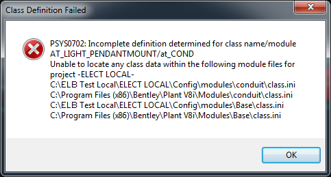
Next, take OUT the Fastener=AT_GLUE lines in JOINTS.INI in all places to ensure that we are really understanding that the AT_GLUE is somehow (magically) called because it is in the JOINTS.INI file – save the file and RESTART AutoPLANT (then the changes will take effect). – Hey – the joint has disappeared as expected. Lets replace the Fastener=AT_LIGHT_PENDANTMOUNT – a custom class and see if it draws that (which is a little silly -but proves a point). Thus the final line I am going to attempt is
[GlueF]
End1 = GLM
End2 = GLF
ReqMatch = ND
Fasteners = AT_GLUE; ELB_LUMISAVE_420LIGHTS
Description = Glue Joint
Tolerance_Variable = MAX_WELDSLOPE_TOL
Restart AutoPLANT/AutoCAD and lets place a peice of rigid pipe down and connect it to another. Well… the idea worked since I got this error message meaning it was looking for files along a certain search path – so the idea works. Now we can go about making our own components have “stuff attached” to it that will show up in the BOM or MTO.
