Creating a class for the new function using an existing class
- Open the class editor, then select the desired path.
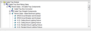
- Open any of the functions in the same subfolder that you want your function to be in.
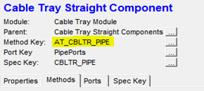
- Copy the name of the “Method Key”, then search for the files in your porject directory using notepad ++ or a similar tool, using the file extension .ini. This will locate the folder in your project directory that the class should be placed in.
- There are 3 files which you need to place information into to create the class. These are class.ini, methods.ini and speckey.ini (speckey.ini is only needed if your function requires you to get data from a database file).
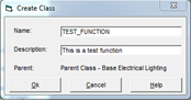
- Create your new class by right clicking on the parent class and selecting “insert new component”.
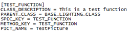
- Enter a name and description. The name is the function that will be called from
AutoCAD, it should have no spaces and be all upper case letters. The
description is what will appear in the class editor, this name can include
spaces and doesn’t need to be uppercase. For example my name is TEST_FUNCTION, and the description is “This is a test function”.
- Clicking Ok will open your new class with default parameters associated with the parent. We need to change the Methods and the Speckey. To modify the methods click on the button ‘…’ to the right of it.
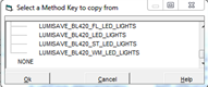
- This will open the method’s dialog box, click on the ‘new key’ button on the right side of the dialog box. The name asked for by the new window will follow the same rules as the name in step 6.
- Copy the same method key as the existing class you are basing your function off of. The functions called will stay the same as the ones in the method key you copied, they can only be changed from the methods.ini file.
- Repeat steps 7-9 for the speckey, the speckey name and the methods name can be the same. Like the methods the speckey can only be edited from its speckey.ini file. When done click the save button in the Class Editor.
- Open the class.ini file, new classes appear at the bottom of the file. Once you have found your class you can change the description, the method or speckey it uses and the picture that will be seen in the class editor. If no picture is desired
then this line can be removed.
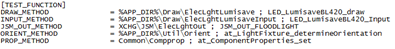
- Open the methods.ini file, the new methods appear at the bottom of the file. In your method you can change the file location and function name of the sub-method, such as the DRAW_METHOD. Change the desired sub method file location and function so that it looks like %APP_DIR%\file_folder\file_name ; FUNCTION_NAME
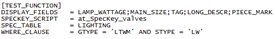
- Open the speckey.ini file. The DISPLAY_FIELDS indicate which fields from the
database file are displayed when the function is run, the fields are shown in
the order they are written, the data will then be sorted alphabetically starting with the left most column. SPECKEY_SCRIPT should be left alone. The SPEC_TABLE indicates which table from your database file information will be used from. The WHERE_CLAUSE filters the data from the selected table, this section works in the same way as an if statement. Only rows that satisfies the clause will be displayed.
Adding a function to AutoCAD Menus, Tool Paletts, Tool Bars and Ribbons
- In AutoCAD open Tools->Customize->Interface.
- Under the Command List select any command and choose duplicate under the right click menu.
- Select the duplicated command (it will have the larger Element ID #), then change the command name to one that describes the function (this will be what appears in
the menus and tool palettes. It will appear as a description in the ribbons and toolbars). - Change the macro so that it is ^C^C(at_Component_insert “AT_CABLET” “CLASS_NAME”),the first “” is dependant on which folder in the class editor you placed your class in. The second “” must be the name of the class that uses your function.
- Select a button image, this is what will appear in the tool palette and ribbon, if
there is no premade image in the list that fits your function create one using
the edit button.Note : any changes made to the command name, description or picture will not automatically update. The command must be replaced in all menus, tool palettes and ribbons.
Menus
- Under the “Customizations in Main File” select at_elect.cuix in the dropdown menu. This will allow changing menu items under “Raceways”.
- Open menus->raceways, then either create a new sub menu under raceways or open more sub menus to reach a desired location.
- Select your command from the Command List, then click and drag the command to the desired location.
Tool Palettes
- Open the desired tool palette, if it doesn’t exist create it using the customize
palettes (from right clicking on the tool palette), right click the palettes
box and select new palette. Name the palette to describe the tool set - Now open the customize user interface window
- Select your command from the command list and drag it onto the tool palette
Ribbons
- Under the “Customizations in Main File” select at_elect.cuix in the dropdown menu.
- Open Ribbons->Tabs->Raceways, right click on raceways and select new tab. The tab name is what will appear on the ribbon
- Open Ribbons->Panels, right click on panels and select new panel. Name it the same as the tab you just created
Building the Ribbon Panel
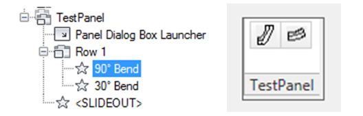
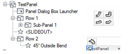
- Ribbons are based on 3 elements, rows, sub-panels and the ‘slideout’
- Rows
- Functions placed in a row will appear left to right evenly spaced, with their order base on their position in the dialog top to bottom
- Multiple rows on the same level will make columns
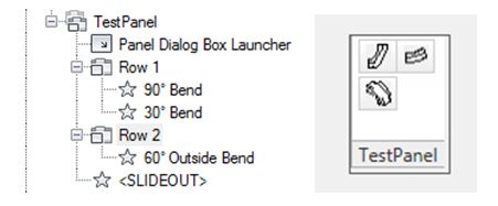
- Sub-Panels
- Sub-panels allow rows to be divided into multiple rows
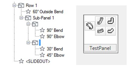
- SlideOut
- Anything below the slidout will appear only when you place your mouse over the slideout, must be on new row that is beneath the slide out
- All functions are added to ribbons by clicking and dragging into place
Tool Bars
- works using the same principals of the ribbons, except that you can only use a single row and there is no slideout
- create a new tool bar by opening the customize user inter face, going to at_elect.cuix. Open the Tool bars folder then right click on it and select new tool bar.
- to place commands on your tool bar click and drag them to the desired location. adding “Flyouts” to the toolbar will create a dropdown similar to the ribbon slideOut when selected. Adding a flyout will also create a separate toolbar that is identical to what is in the flyout